What bundle do I choose?
Scan-to-CAD and mesh editing software explained
Thor3D offers a variety of bundles for designers, 3D artists and engineers. Before picking the bundle, it is essential to understand what lies in the core of 3D modelling.
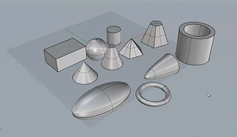
SOLID MODELLING
In solid modelling, an engineer creates a mechanical part out of solid primitives partially imitating the process of manufacturing (extruding, drilling). Solid modelling is parametric, meaning that the change of one parameter inevitably leads to the changes in the adjoining ones. The model has a parametric history (the tree) and the engineer can always trace back to the previous stage of the model and change it.
SURFACE MODELLING
Surface modelling is best used when creating a freeform or organic object. It is not parametric, doesn’t have a history tree and is hard to change. Surface modelling constructs the surfaces of an object meaning that the object is hollow inside until the engineer builds enough of the surfaces to “lock” the part. This is an important issue in surface modelling, because an object cannot be finished until it has holes in it. Various programs suggest different methods to test if the object is complete, or still has holes.
SCULPTING
As with the surface modelling, sculpting is used in creation of organic/freeform objects. The difference lies in the principle of the model construction: a specialist starts with a stimulated ball of clay and works on an object as a real sculptor. Sculpted meshes usually have millions of polygons, which makes them the “heaviest” 3D models.
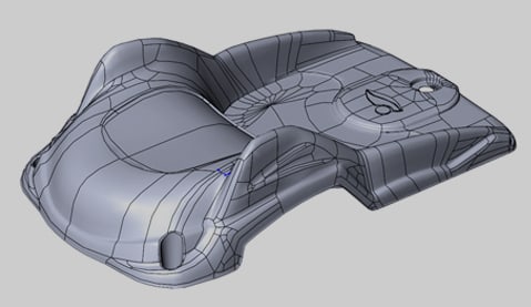
At times it can be confusing what software is best suited for freeform or organic shapes – sculpting or surface modelling software? While the choice depends heavily on the artist’s goals and preferences, we can give a slight hint: product designers, architects usually choose surface modelling software because it helps them control the shape and the topology* of an object simultaneously. 3D artists mostly opt for sculpting software, because it concentrates on the shape only.
*Topology is the patterns of polygons, which construct the mesh.
Image 1. Proper topology of a model created with the help of surface modelling.
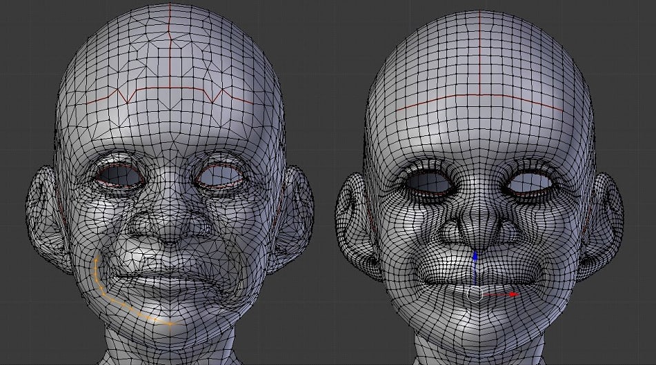
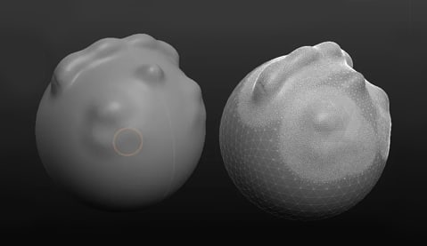
Image 2. A comparison in topology. A model on the right might be well suited for animation, while a model on the left can serve only as a concept idea.
BUNDLE MATRIX
In order to navigate among Thor3D’s bundles better, we suggest using the Bundle Matrix. We shall also provide a detailed description to each bundle, so you can make the best choice for your customers.
MESH-TO-CAD OF MOSTLY MECHANICAL PARTS
Complex high-end solutions
Geomagic Design XRhino
Industrial Scan Data Reverse Engineering
Approachable high-end solutions
Geomagic for SOLIDWORKSQuicksurface
BUNDLE FOR DESIGNERS, 3D-MODELLERS, ARTISTS
Complex high-end solutions
RhinoZbrush
Approachable high-end solutions
Geomagic Wrap
MESH-TO-CAD OF FREEFORM SHAPES
Complex high-end solutions
Geomagic Design XRhino
Approachable high-end solutions
CyborgQuicksurface
In the matrix we highlight five customer segments: (1) engineers (who need mostly solid modelling), (2) product designers (who usually work with surface modelling of freeform shapes), (3) 3D artists and sculptors, (4) beginners and (5) quality control specialists.
Detailed bundle description
GEOMAGIC FOR SOLIDWORKS
A plug-in from 3D Systems, which allows work directly in Solidworks. This plug-in combines the tools from Geomagic Design X
and Solidworks, providing quick workflow with both freeform shapes and engineering parts.
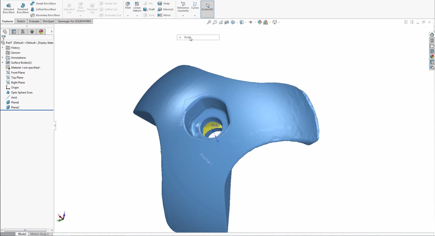
Image 3. Geomagic for SOLIDWORKS interface. The work on the mesh is done in several tabs (Geomagic tools and Solidworks tools).
The plug-in is distinct for well-known algorithms from Geomagic. You can quickly do automatic segmentation of the mesh into separate primitives, which later will be extracted into solid bodies.
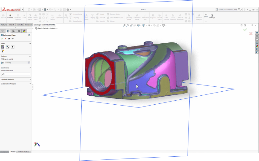
Image 4. An example of auto-segmentation. In Geomagic for Solidworks this feature is called “Regions”.
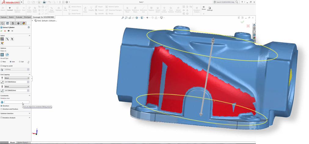
Image 5. The software recognizes the cylinder, which can be extracted into solid body.
QUICKSURFACE
Quicksurface is a stand-alone program, which is compatible with Solidworks (able to save the history tree and export it into Solidworks with a model). Made specifically for those users, who are new to reverse engineering, it offers the most essential tools.
Even though the software has the same mesh-to-CAD logic as its peers, it has a couple of interesting interface solutions. For example, the developers made a more visual representation of a coordinate systems with easy manual control, meaning that you can move a 3D model along xyz-axis with a mouse click. On the screenshot below it is illustrated that the user can choose the axis from the dropdown menu and adjust the parameters according to the needs.
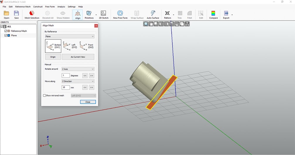
Image 6. A screenshot of Quicksurface interface with a coordinate system.
Most of the tools of the software are manual, the interface is intuitive. The software offers suggestions during each step of the workflow.
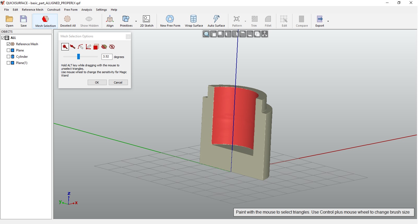
Image 7. An example of the suggestion
However, unlike Geomagic products, the software doesn’t allow amending the mesh if the need arises. This means that you have to import an already prepared mesh (for example, with filled holes, decimated, etc.)
Limited number of manual tools may be extremely helpful when working with simple engineering parts. Complex meshes might require strong engineering skills.
Even though we placed this bundle in the group “Mesh-to-CAD conversion of mostly mechanical parts”, freeform and organic mesh conversion is also possible in Quicksurface. The work with freeform objects is mostly manual, too.
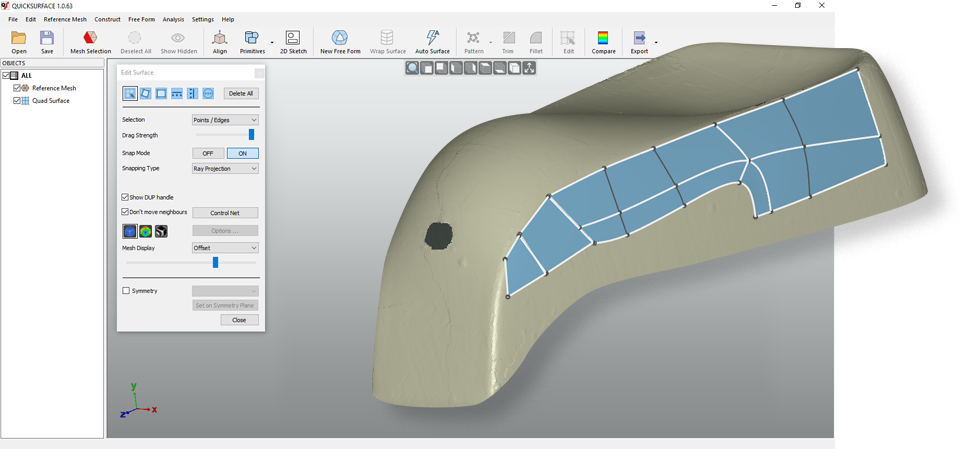
Image 8. Freeform mesh-to-CAD conversion by means of surface modelling.
GEOMAGIC DESIGN X
This is one of the most well-known programs for reverse engineering on the market. The software offers a range of flexible tools for mesh editing and reverse engineering.
In the example below, you can see mesh editing tools (split, trim, enhance shape), which might be helpful when preparing a model for reverse engineering.
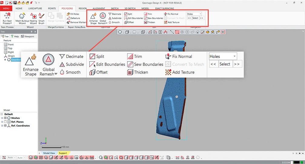
Image 9. An example of mesh editing tools in Geomagic Design X.
As we have mentioned before, Geomagic is distinct for its powerful algorithms, which help to do most of the reverse engineering steps automatically. This means that even the most complex engineering part can be converted from mesh to CAD rather quickly.
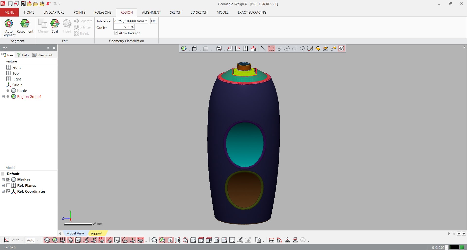
Image 10. Auto-segmentation. A powerful tool, helping to divide an object into geometrical primitives (cylinder, plane, prism and etc) and differentiate a freeform shape. Later, these primitives will be extruded/revolved into solids, or cut out – depending on the task.
Unlike Geomagic for Solidworks, which can export a CAD model with a history tree only to Solidworks, Geomagic Design X offers CAD model export into most well-known CAD programs.
RHINO
Rhino is a stand-alone program most suited for the designers and architects. It is not directly meant for reverse engineering, although it might delineate the mesh by means of the NURBS.( NURBS or non-uniform rational B-spline - is a mathematical model, representing the surface. NURB surface consists out of control points and knot vectors, which determine where and how the control point affects the NURB curve.)
However, these NURB models are hard to edit due to confusing topology. McNeel, the developer of Rhino software, officially recommends using mesh or point cloud only as a reference for modelling.
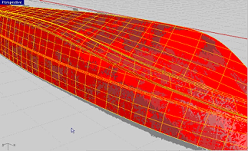
Image 11. A screenshot from McNeel website explaining why direct mesh-to-CAD is not recommended in Rhino. On the image it is clearly seen that the topology of the object is inappropriate.
However, Rhino offers a variety of mesh tools, solid tools and rendering tools, which allows you to create almost any model desirable. What makes the software particularly flexible is the ability to add control points to the curves of surfaces and change the drawing according to the needs. This enables the users to have more control over the 3D model. The video below shows how control points and knots affect the model:
GEOMAGIC WRAP
Geomagic Wrap can also be used for reverse engineering, but it has some distinct features, which make it different from Design X. So, aside from converting a mesh to CAD (compared to Design X it has limited number of mesh-to-CAD tools), you can also work on its textures (side not: Rhino and Zbrush allow texture edits too).
For example, you can apply texture to your model, amend the color and adjust its brightness/contrast, implement RGB corrections and etc.
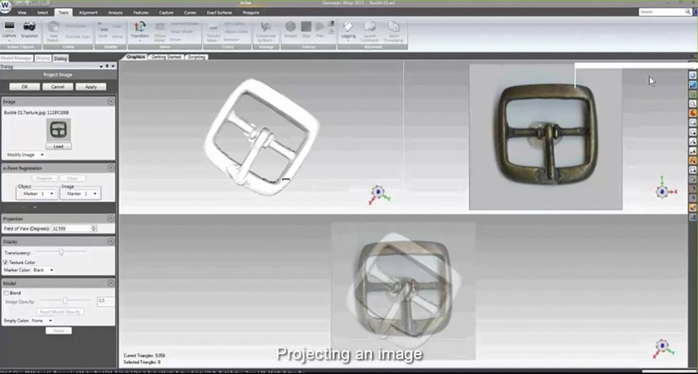
Image 12. On the screenshot a .jpg texture is applied to the model.
Geomagic Wrap also enables you to unwrap the model as on the example below:
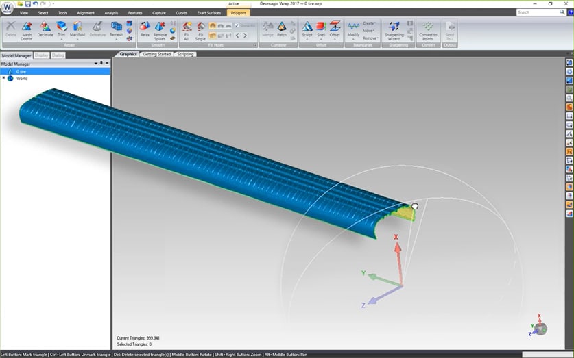
Image 13. A 3D model of a tire has been unwrapped around the Z-axis.
Aside from texturing tools, Geomagic Wrap has some useful measurement tools.
You can also scan directly into Geomagic Wrap (like with Geomagic Design X) and align multiple scans into a single scan.
GEOMAGIC CONTROL X
Geomagic control is a stand-alone program designed for quality control and inspection. It is frequently used by the engineers during product design and development stages. It enables to compare mesh data to CAD model and evaluate the tolerances, deviation, build linear trends and etc. The software also allows the user to export statistical reports in .pdf-format.
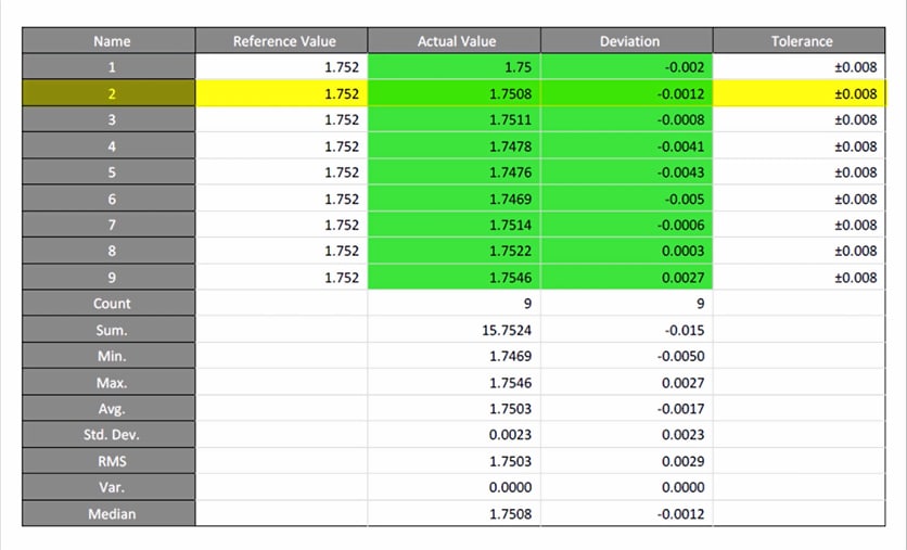
Image 15. An example of the report made in Geomagic Control X.
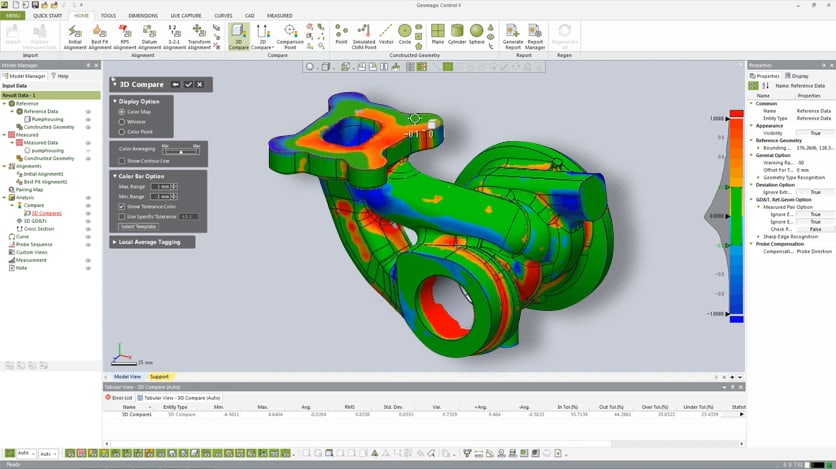
Image 16. A sample of Geomagic Control tools for mesh&CAD analysis.
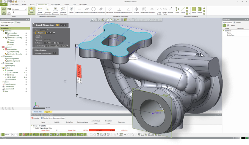
Image 17. Assigning dimensions to the model.
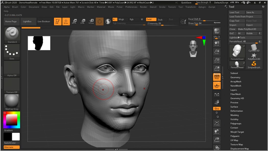
ZBRUSH
Zbrush is a stand-alone software, which enables you to create 3D models from scratch using sculpted mesh. The users can also use this bundle to repair a scanned mesh, correct texture and even edit the mesh like the way you would Photoshop a 2D image (for example, Zbrush enables you to painlessly remove tiny details, for example like arm hair from the human scan).
VERISURF
Thor3D and Verisurf have create special bundles for their customers:

INDUSTRIAL SCAN DATA REVERSE ENGINEERING BUNDLE
Industrial Scan Data Reverse Engineering Bundle comprises CAD and REVERSE modules from Verisurf suite. Verisurf Reverse creates surfaces and features to create CAD model. It creates custom-fits lines, arcs, splines, planes, spheres, cylinders and even freeform surfaces.
Verisurf CAD module enables users to import all popular CAD formats. The architecture of the program allows to create custom tools to fit the users’ specific needs. Model-based Definition (MBD) lets users set unique IDs and tolerances in the model for any surface or feature.
INDUSTRIAL SCAN DATA INSPECTION BUNDLE
The bundle comprises CAD and ANALYSIS modules. With analysis module the user can easily analyze the CAD model with a click of a button: analyze points-to-points, points-to-curves, points-to-surfaces or points-to-meshes and generate deviation reports. The program generates the report in Excel file and HTML-based color reports, including color deviation mapping.
EDUCATION BUNDLE
This bundle was specifically designed for educational institutions. It provides the most essential Verisurf modules for a complete metrological or reverse engineering tasks. The Suite includes CAD, MEASURE, BUILD, ANALYSIS, REVERSE, and AUTOMATE modules.
CYBORG
Cyborg enables the users to convert into CAD sculpted meshes (Zbrush models) and scans of organic forms.
The process can be done in 6 simple steps:
1) Run Quad Wrap Mesh. That means, that the model will be divided into quads, which follow geometric curvature flow.
2) Check for open edges. CAD models have to be watertight, so Cyborg offers an automated algorithm to check for open edges. If the mesh is watertight, Cyborg will inform the user about it.
3) Use Shrink Wrap tool to add detail to the quad mesh without adding extra polygons.
4) Fix self-intersections that might have occurred after running previous features.
5) Convert the mesh to a Brep NURBS format
6) Export CAD model
The software allows to control knot density, which helps to keep the model hi-res and “light-weight” at the same time.
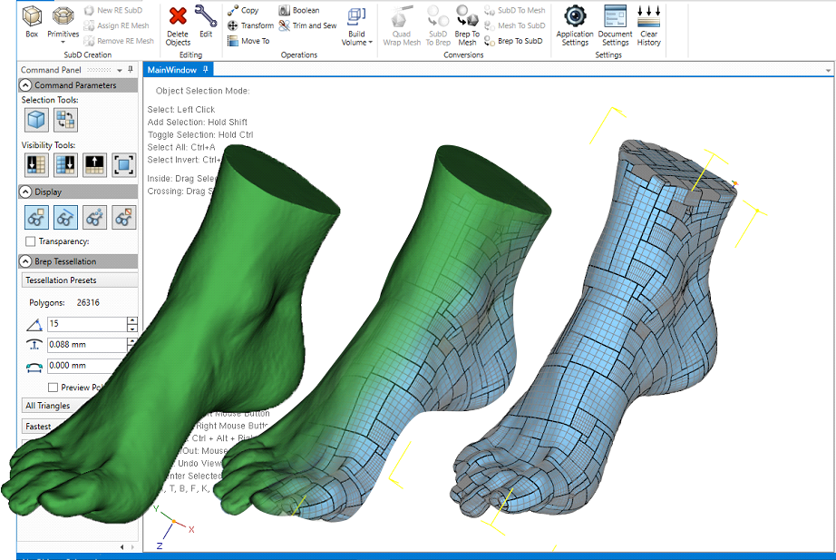
Image 19. Cyborg interface.